Ok, So I realize that I'm editing and updating this blog in reverse.. but so be it. Anyway, here's another little update on the progress with these bevel gear / robot arm joint project. It moves! It knows where it moves!
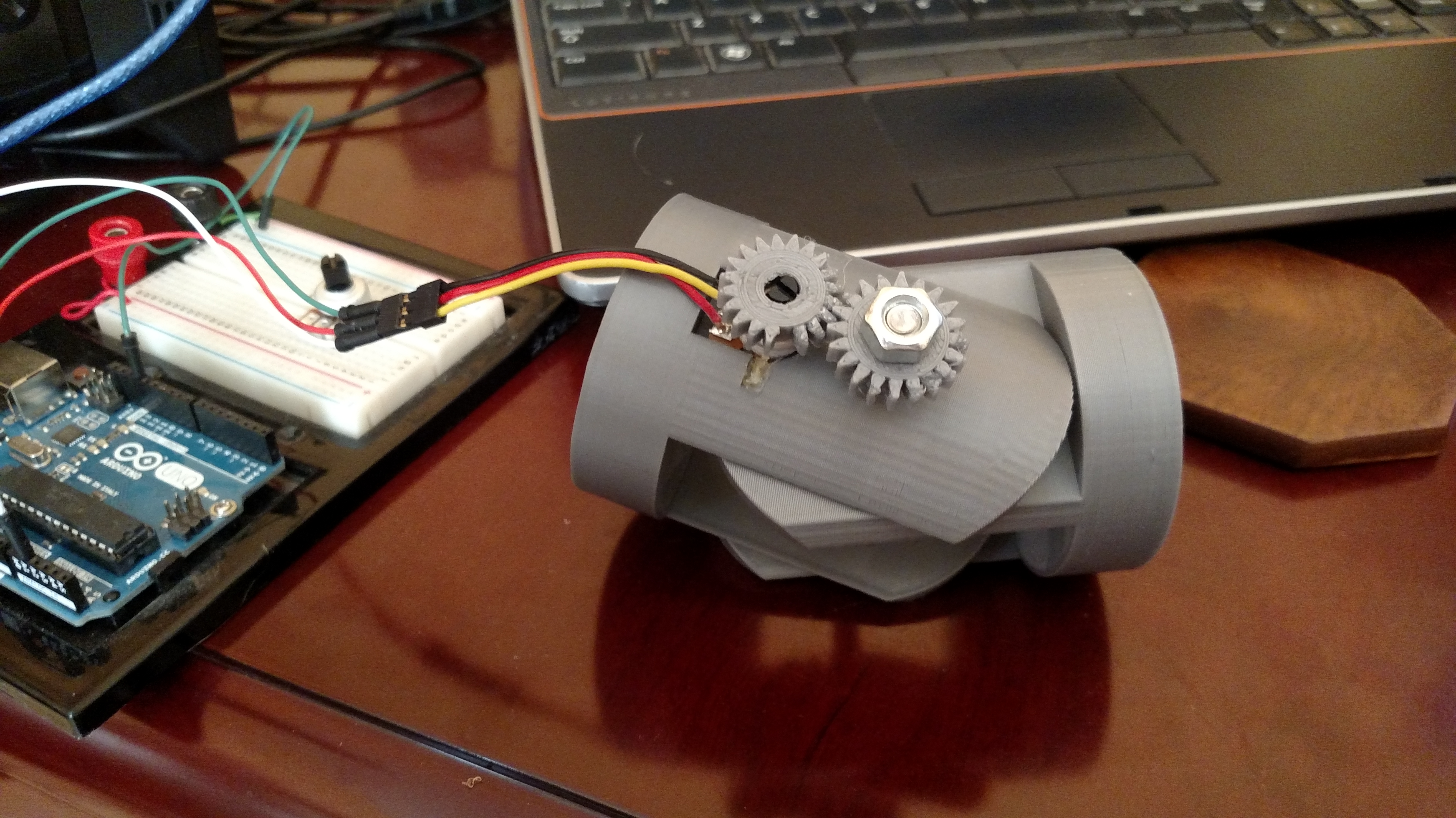
Another Update. I've attached 2 small gears, one to the screw (which is connected to the frame) and a second one to a pot that is recessed on the frame. As the joint rotates, the screw rotates and causes the pot to turn .
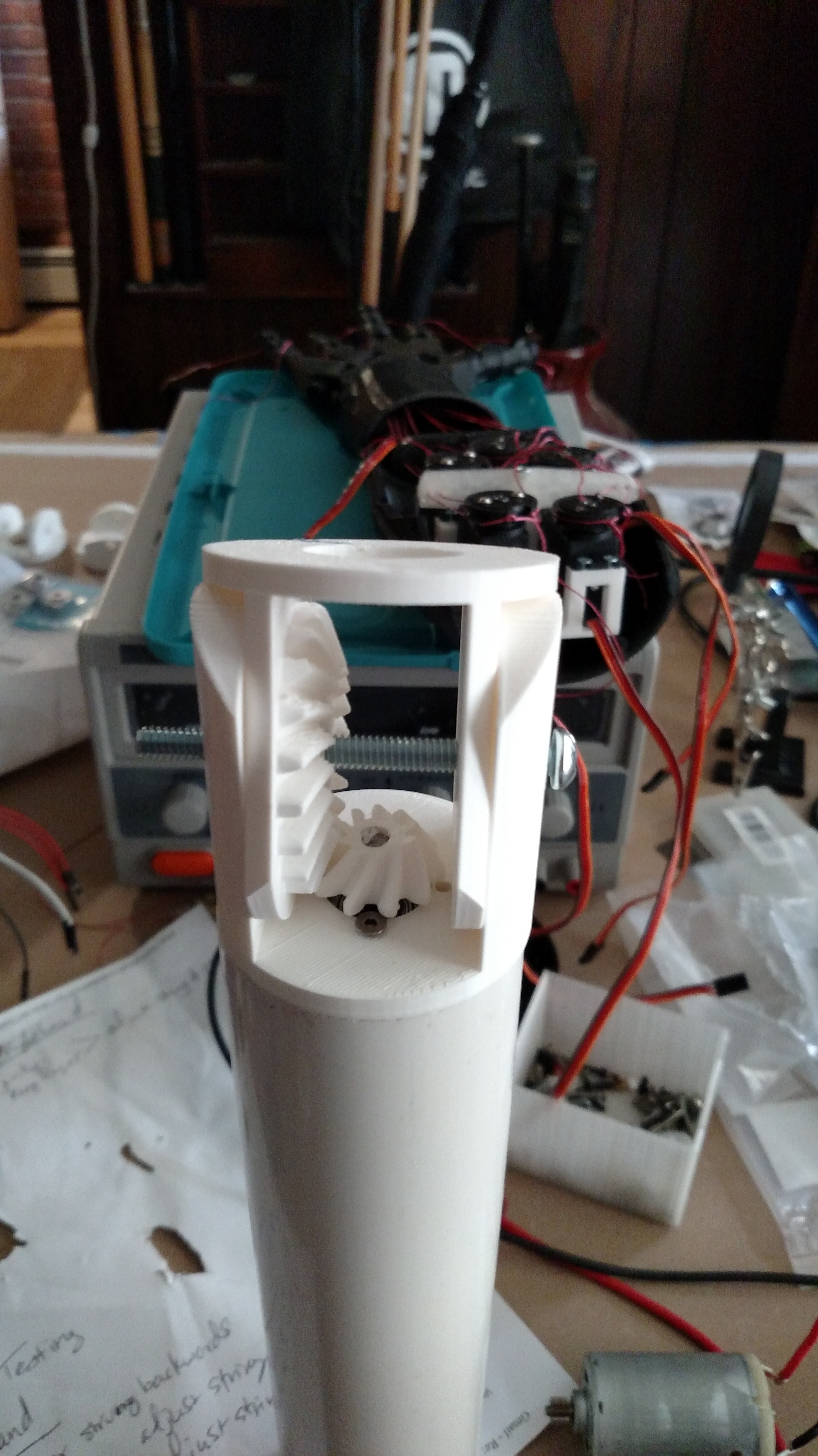
Ok, so Update: I've been printing these gears for about a week now, and I finally have a 6 degree of freedom robot arm that uses these gears with some pvc pipe couplings between them. They're designed to work with 2" standard pvc pipe that you can pick up at your local hardware/plumbing store.
This assembly is really just intended to show how these could be cascaded together to acheive a high degree of flexibility.

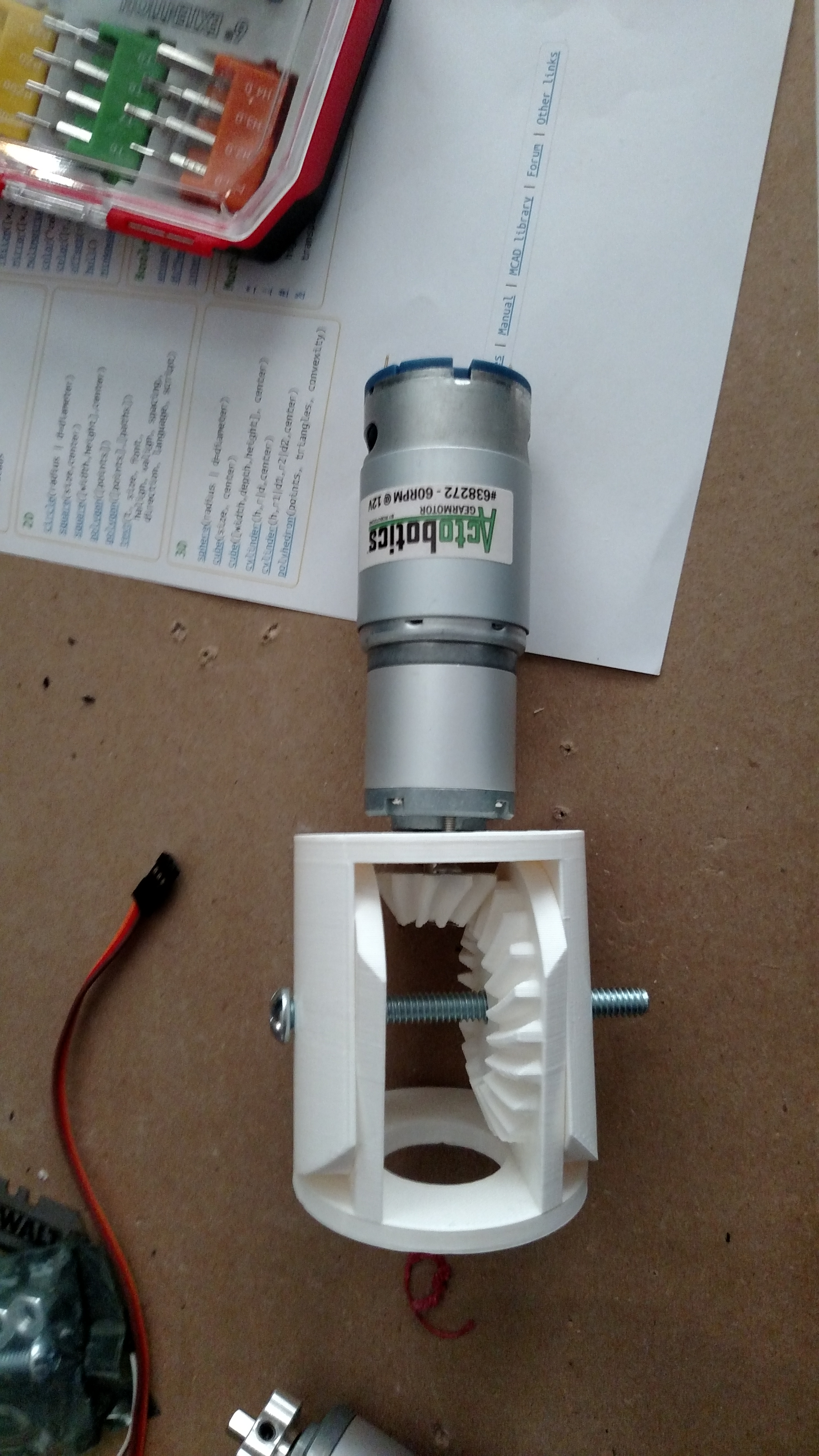
I'm thinking of monting a gear motor in the a hinge joint by using a bevel gear to connect the motor and the rotation of the hinge joint at a right angle. 3D models are a work in progress.
I'm desinging for a 37mm DC motor with a planetary gear hooked up to it. My test motors operate at 60 RPM ( @ 12V )
Here's a quick little screen capture of the parts I am working on...
hello kwatter when i see your
hello kwatter when i see your work it is exactly what i thinking about elbow arm robot
it is possible you give us your stl files?
thank you amby
Ehi Kevin... Are you having
Ehi Kevin... Are you having problems with the motor shaft rolling in the gear hole? What I mean is... Does the turning of the motor make the hole bigger and the motor shift becomes loose with the gear?
still testing
hey ale, right now, i'm still working on the design of the parts. Initial tests look like it's pretty strong. I need to redesign the motor mount. The major issue I had is the gear connected to the motor shaft strips out, so I needed to get a mount that I could screw the 3d printed gear to. Those just arrived!
The next thing I've gotta add to the model is a place to put the pot!
ciao!
Duplication.....
That's coming along nicely.
How about mirroring the gears ie having both the big left & right bevel gears also the small up & down bevel gears (so it looks kinda like a car differential unit)
The gears will all mesh together giving more all-round rotational support/drive and the extra small gear could drive the potentiometer.
differential gears
Gareth, you have some great ideas!
I was originally thinking some like a differential, but it seemed a bit more complicated to design.
Is the following an example of what you were thinking?
https://www.youtube.com/watch?v=Md0vrDyU_yg
I think the direction of rotation would be opposite for the two big gears if they are directly connected to the driving center gear. Maybe I could attach one of the big gears to the bottom peice and one to the top piece. Maybe the counter rotation would be ok in that configuration... (even desirable)
I do like the idea of having more gears touching to spread out the load / torque. I think for now, I'll keep it simple to test some basic functionality.