So the small ATMEGA328 Board need a small program inside that read my rotary encoder and turn the motor to the position he recieve from the Ardiuno Mega pin 8 . So when ArdiunoMeg give command like to a servo he must respond same way as servo.
Can you do this. Or do i understood it wrong what is possable.
I would have answered you sooner, but I'm in Germany working. Lots of work work... long days here and jet lag make me want to sleep when I'm done with the day.
But I think this is a great project you are working on !
The first thing which came to mind ..
I think its impressive you want to make this "behave" like a servo, but I think your trying TO HARD ! Bit-Banging an RC signal would be ineffecient and prone to errors.
I would prefer to support it from MRL as a real DC Motor with a single channel encoder.
Which means you should not need the additional Mega to be connected to it. I believe you can directly connect an FTDI cable to it. So you'd run MRLComm.ino on the motor controller directly.
There are only 2 pieces which would need to be added.
MRLComm.ino needs to support a DC Motor with a single encoder such that MRL can send the motor to moveTo(170) and MRLComm.ino would start the DC motor at a specified and appropriate PWM speed. Count the nnumber of pulses from the encoder, and stop (possibly ramp down) the motor at the appropriate 170 pulse.
Motor and Servo need a common interface in MRL-land .. So that you can use any of the Python scripts currently written for a Servo to work on your new "Motor-Servo"
Grog please i must realy tri. Any small program that i can tri load in the Baby Arunutang please. It have like the picture shows buildt in motor driver and have everything. I know you can do this please
Ok - They have a library, we do not want it - but I need to find out details about the H-Bridge.
Clever product tiny Arduino + Dual H-Bridge - theoretically, you should be able to drive Massive Adolph Servos from this board. I see it uses pwm for speed control which is what I would expect - what I don't see at the moment is if its a :
Evil Dirty H-Bridge - where direction and speed are controlled on the same line but 2 pins - and it has a evil shoot-through state .. or
Happy Good H-Bridge - where direction pin is seperate from the speed pin
I'm hoping for the latter - but haven't found the answer yet.
At this stage i am bad. I hooked everything up but can not find any skettch that i can use with motor and rotary encoder/ So i am realy stuck . Have every thing but no test without test script(Library) Mi connections is exactly as my first drawing in this blog .
Adolph, did you try uploading a sketch to use the baby board without encoder? The encoder can be added easely, if you test with the scripts from the polulu site, you can test speed, direction and so, and after grog gets back i think he can build a simple sketch with an encoder in it to use as dc motor/servo with poti.
Cause and effect - upload a simple blink program, does it work ?
Unplug everything from the Atmega 328 if you need too except the FDTI cable.
This is the first check. If it worky - you say "WORKY !" and we move on to Step 2 - if it no worky - we find out why..
Sory Grog what i ment was that blink leds working but other things not like motors.I have tested with blink led yes. Worky. Now for something in scrip that let motors run. Because all the scrips available need pot to get motors running. I do not use pot .
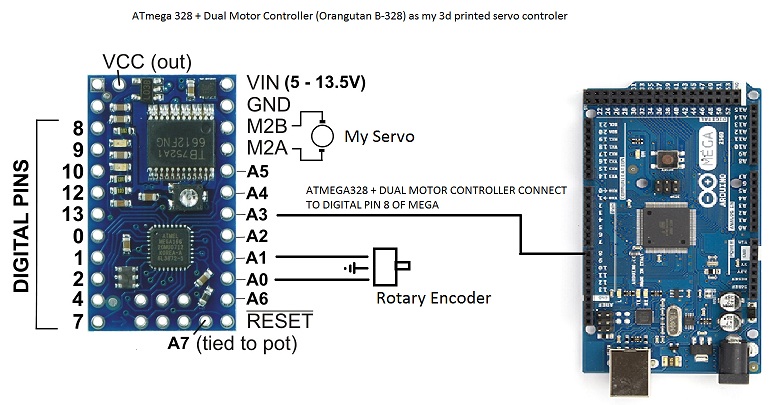
I have Used a ATMEGA328 +
I have Used a ATMEGA328 + DUAL Motor Controller ( https://www.robotics.org.za/index.php?route=product/product&product_id=…) as driver for my DC Servo motor.
Inside also a Rotary Encoder ( https://www.robotics.org.za/index.php?route=product/search&search=rotar… ) .
So the small ATMEGA328 Board need a small program inside that read my rotary encoder and turn the motor to the position he recieve from the Ardiuno Mega pin 8 . So when ArdiunoMeg give command like to a servo he must respond same way as servo.
Can you do this. Or do i understood it wrong what is possable.
Thank you
Adolph
Adolph
Ahoy Adolph, I would have
Ahoy Adolph,
I would have answered you sooner, but I'm in Germany working. Lots of work work... long days here and jet lag make me want to sleep when I'm done with the day.
But I think this is a great project you are working on !
The first thing which came to mind ..
I think its impressive you want to make this "behave" like a servo, but I think your trying TO HARD ! Bit-Banging an RC signal would be ineffecient and prone to errors.
I would prefer to support it from MRL as a real DC Motor with a single channel encoder.
Which means you should not need the additional Mega to be connected to it. I believe you can directly connect an FTDI cable to it. So you'd run MRLComm.ino on the motor controller directly.
There are only 2 pieces which would need to be added.
Does this sound desirable to you?
Thank you. I will tri to
Thank you. I will tri to program Baby ardiuno if i do not succeed i will do this. Thank you.
Grog please i must realy tri.
Grog please i must realy tri. Any small program that i can tri load in the Baby Arunutang please. It have like the picture shows buildt in motor driver and have everything. I know you can do this please
Do you have a FDTI cable - so
Do you have a FDTI cable - so you can program the Orangutang ?
Can you post a picture of your current setup?
(No subject)
Grog i hope this is what you
Grog i hope this is what you ask
Perfect Adolph ! Ok - They
Perfect Adolph !
Ok - They have a library, we do not want it - but I need to find out details about the H-Bridge.
Clever product tiny Arduino + Dual H-Bridge - theoretically, you should be able to drive Massive Adolph Servos from this board. I see it uses pwm for speed control which is what I would expect - what I don't see at the moment is if its a :
I'm hoping for the latter - but haven't found the answer yet.
Found it
Found it !
https://github.com/pololu/libpololu-avr/blob/master/src/OrangutanMotors/OrangutanMotors.cpp
Now I have to understand it :)
Good news its a Happy Good
Good news its a Happy Good H-Bridge !!!
So it looks like a simple pwm pin for speed & direction is on another pin...
We need to find out exactly what pins your current motor is hooked up to - what are they?
The next step would be to make a very small sketch which drives the motor WITHOUT Pololu's Motor library.
Have you driven this motor with Pololu's Motor library yet?
What experiments have you done so far Adolph?
At this stage i am bad. I
At this stage i am bad. I hooked everything up but can not find any skettch that i can use with motor and rotary encoder/ So i am realy stuck . Have every thing but no test without test script(Library) Mi connections is exactly as my first drawing in this blog .
http://myrobotlab.org/sites/default/files/users/user884images/Servo%20M…
Adolph, did you try uploading
Adolph, did you try uploading a sketch to use the baby board without encoder? The encoder can be added easely, if you test with the scripts from the polulu site, you can test speed, direction and so, and after grog gets back i think he can build a simple sketch with an encoder in it to use as dc motor/servo with poti.
Small simple steps will win
Small simple steps will win the Race !
Step 1
Cause and effect - upload a simple blink program, does it work ?
Unplug everything from the Atmega 328 if you need too except the FDTI cable.
This is the first check. If it worky - you say "WORKY !" and we move on to Step 2 - if it no worky - we find out why..
Sory Grog what i ment was
Sory Grog what i ment was that blink leds working but other things not like motors.I have tested with blink led yes. Worky. Now for something in scrip that let motors run. Because all the scrips available need pot to get motors running. I do not use pot .
I looked at some of the
I looked at some of the documentation & the libraries code.
I "think" PWM power is controlled by pin 6. If that is correct a simple analog write should change the motors speed.
Try this
[[home/GroG/servoMotor.c]]
If that works we can start thinking about the feedback of the encoder. I hope your still interested in doing this !
Yes i must get this working
Yes i must get this working thank you
// F_CPU tells util/delay.h
This is message what i get of new script
This is working
Motors need power and under
Motors need power and under 40 it dont start
So when you comment
So when you comment out
//motors.setSpeeds(128,128);it doesn't work ?
That's the goal Adolph, not to use the motors.setSpeed and still be able to move the motors .. :)
If you
If you do
//motors.setSpeeds(128,128);(No subject)