The CYS-S8218 is a nice beefy servo boasting a 40Kg of torque, which is very impressive.
However, this servo does come with one limitation; it has only a 90 degree of rotation output.
When you look inside the servo, there at physical stops at 220 degree and the position potentiometer is also rated to 220 degree, this suggest a lot of reserve capacity within the mechanics, and the manufacture wanting to prevent model builder from overloading the servo by limiting the range to a point it will always have max torque available.
In our application, turning a screw, we need all the rotation we can get and the torque doesn’t really change over the entire range.
Having had a look inside, I found it was possible to modify these servos by adding resistors to the position sensing potentiometer, I was able to double the range using this method.
Please note, my photos show the servo mounted in a holder, it was difficult enough to get it into the holder and doesn’t prevent me from working on it, so I left it in the holder.
For those who are interested, the holder is part of the Bartosz designed legs for his robot Damian.
You can find the file on Thingverse at https://www.thingiverse.com/thing:2316843
you can also see his blog on his progress at http://myrobotlab.org/content/progress-damian-legs
Let’s have a look at the beast:
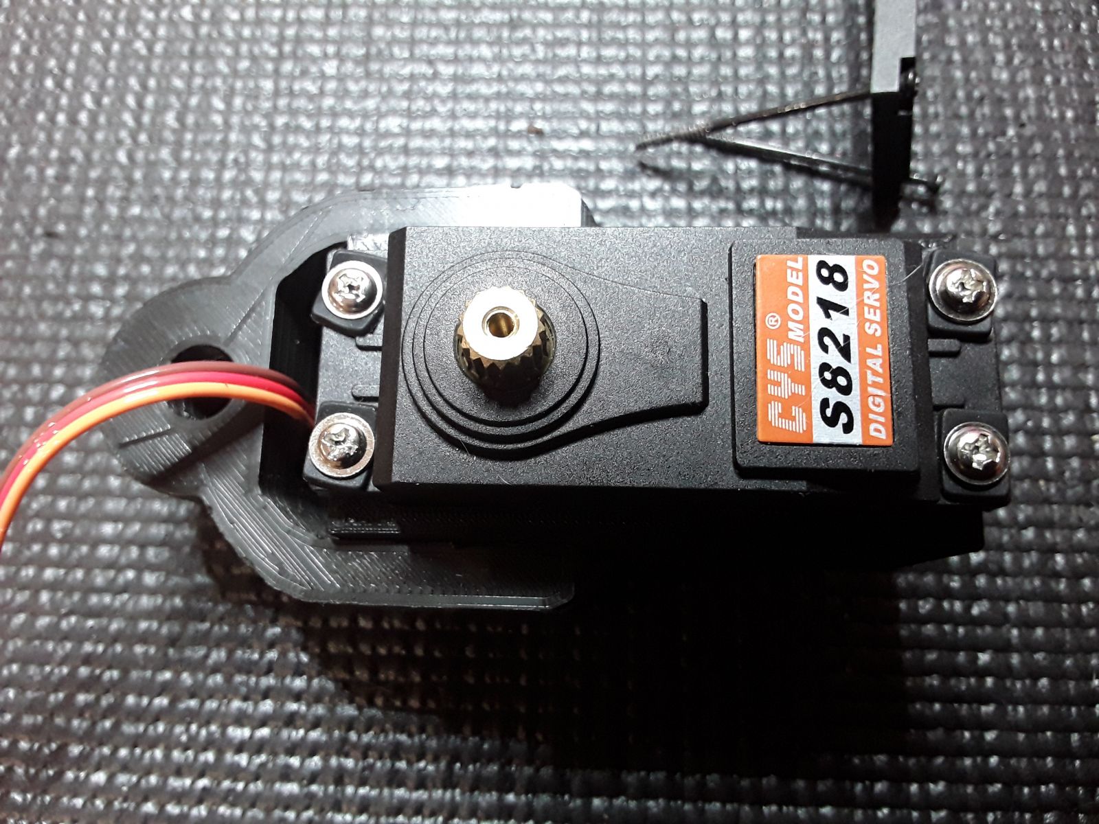
From the outside it does feel very solid, does not move on power up until you tell it to, runs very smoothly.
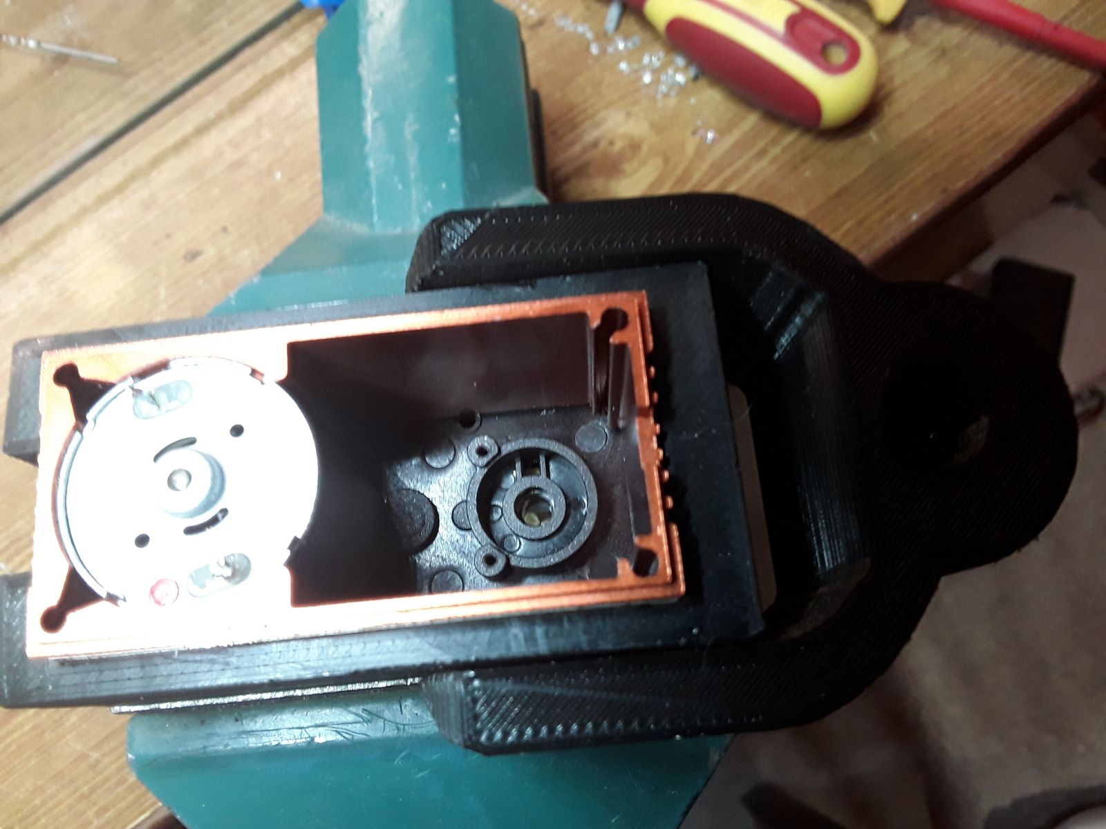
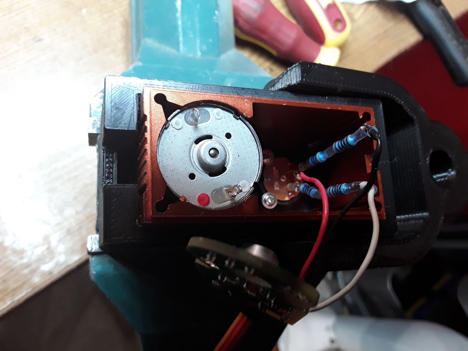
With the back cover open, the electronics are shown and the extent of the housing is also shown.
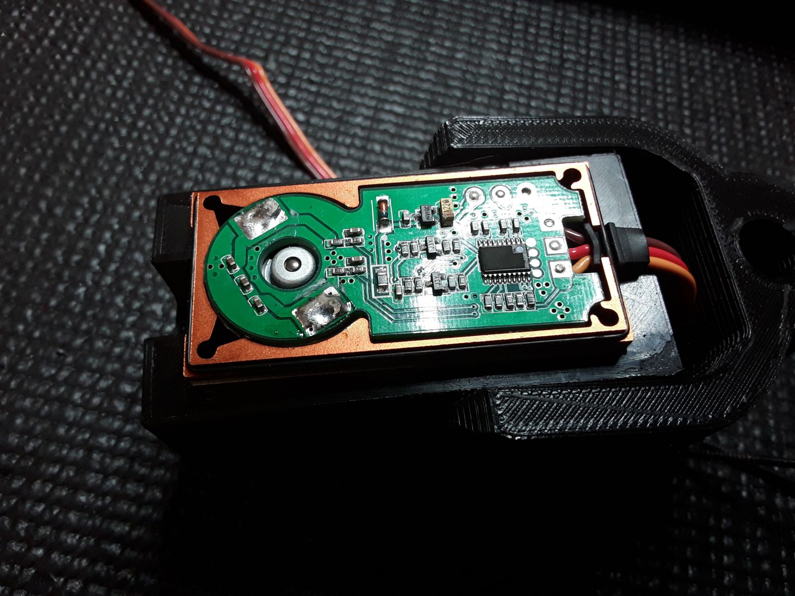
As you can see the housing makes close contact with the motor, this allows the housing to dissipate some of the heat created by the motor allowing it to last much longer under heavy load before burning out. On the down side, the manufacture removed the numbers off the controller chip :-(
To get at the potentiometer, located below the circuit board, we will have to de-solder the motor.
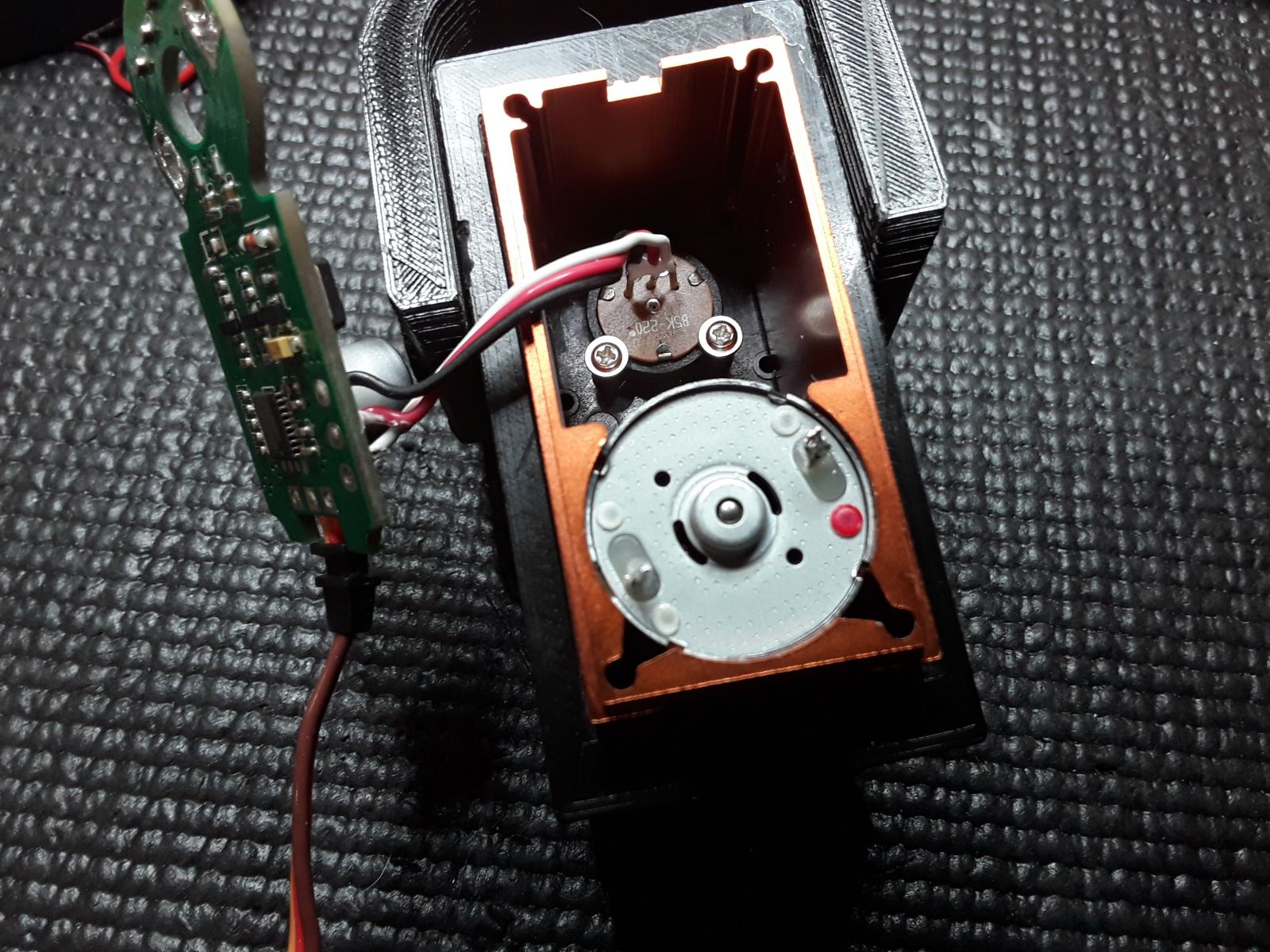
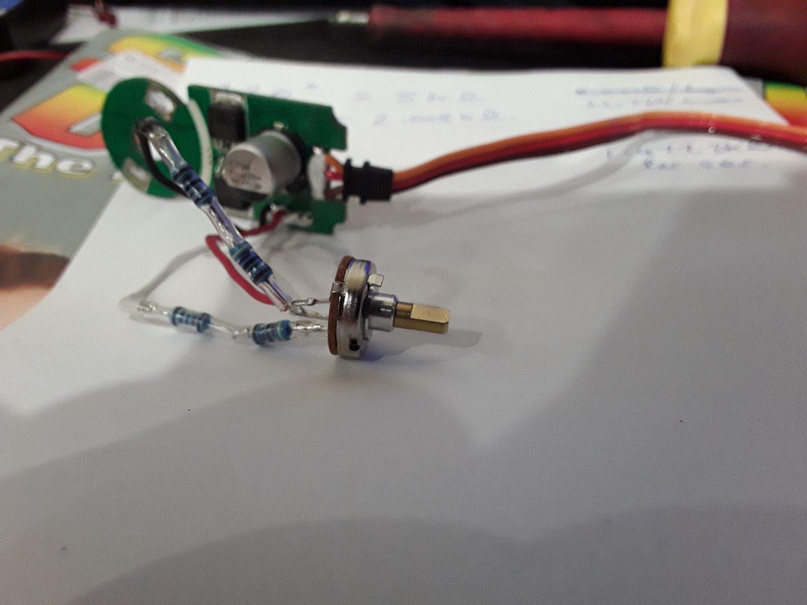
Once de-soldered the circuit board can be removed, but be careful of the 3 wire that go to the potentiometer. To work on the potentiometer we will need to remove it as well. As you can see it’s held in by two small screws, remove these and carefully withdraw the potentiometer.
Note that the potentiometer marking shows it to be a 220 degree rotation and has a resistance of 5K ohm.
We will need this information later to select the resistors.
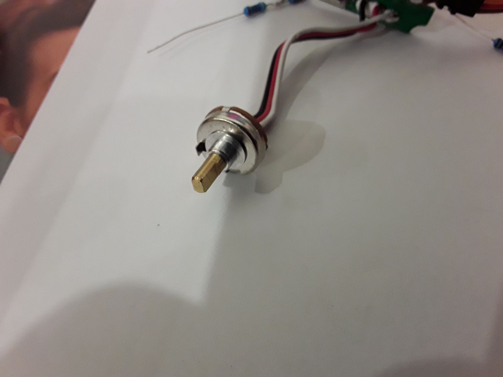
Take care not to turn the potentiometer as it is keyed into the output gear and the tag on the side is keyed to the casing, if you rotate the potentiometer shaft, you may find it very difficult to put back in.
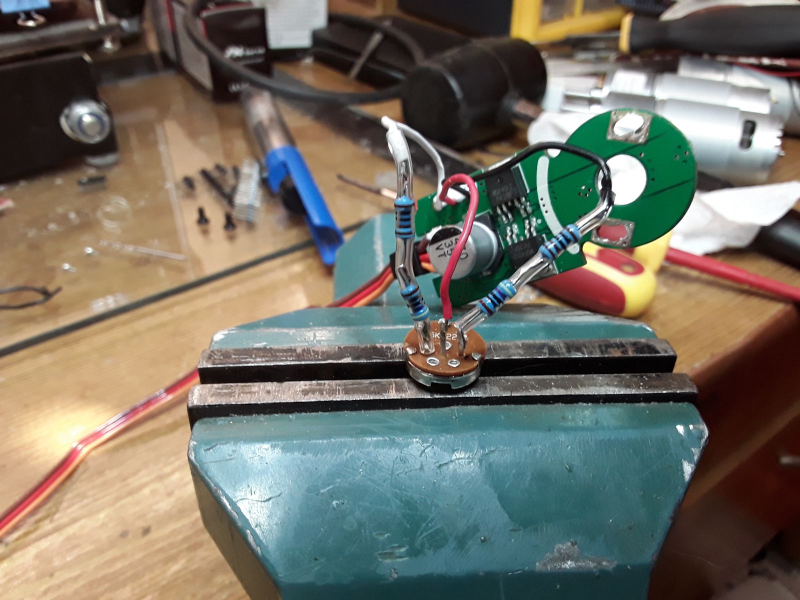
With the potentiometer now out and easy to access, you will note from these photos, the red wire is connected to the wiper while the black and the white wires are to each side. We will need to add a resistor to each of the outside wires, but we must be very careful not to swap the wires around. For this reason I suggest working on one wire at a time, preventing any possibility of mixing them up.
Now for some maths:
We know the entire range 220 degree is 5000 ohms, and we also know that the wiper is centre of it travel when the servo is centre of its travel, I tested this before disassembly, I also have a video of the testing with the gearbox side open https://www.youtube.com/watch?v=YXdwGzQF46s&list=PLgXTfFM40HqF9W8J3BK041oXowSTzH2ct&index=1
If we divide the 5000 ohms of the resistor with the full rotation of 220 degrees we get 22.73 ohms per degree.
We know we get 90 degrees of use which is 2045.45 ohms over the useful range.
That leaves us with 2954.55 ohms of useless range, half on each side.
There are a couple of ways to work out the resistance we need: The correct way or the way I used J
I simply started with the total resistance, subtracted the used resistance of 2045.45 and divided the results by two to get 1477 ohms. I didn’t have a 1.47 K Ohm resistor so I used a 1 K ohm resistor and a 470 ohm resistor in series. While this did give me 180 degree, it’s not the correct method.
The correct method would have been to use the ratio between the total resistance and the used resistance or the ration of the current rotation verse the possible rotation, both work out to the same number. 220/90 = 2.444 or 5000/2045.45 = 2.444.
If you multiply the ration by our total pot range you get 2.444 * 5000 = 12222.22. This would be for the whole of the new apparent potentiometer. We now subtract off this the resistance of our real potentiometer to get 7222.22 ohms. This is what we need to add to our pot to give us a useful rage of 220 degrees, but we need the pot cantered so divide this by 2 to get 3611.11 Ohms, the nearest standard size resistor is 3.6 K ohm. This method will give you 220 degrees of rotation.
First you will need to un-solder the wire from the side of the potentiometer.
Next solder one end of the resistor to the potentiometer where you just un-soldered the wire.
Slide some heat shrink tube over the wire with enough length to cover the potentiometer terminal and the resistor.
Solder the wire to the other end of the resistor.
Wait for the joints to cool then slide the heat shrink over the resistor and the potentiometer terminal.
Use a hot air gun to shrink the heat shrink.
Repeat for the other side of the potentiometer.
Once you have done both sides, it is time to re-assemble your servo.
Make sure you align the tab on the side of the potentiometer with the matching notch in the servo housing.
And re-insert the two screws.
You may need to fold down the wires with the added resistors so you can re-fit the circuit board and re-solder the motor terminals.
You would never know we had it apart.
Refit the covers, being careful to re-install the small O-ring seal around the case body.
Now you can test your results.
Have fun with your robots, remeber this is a hobby, so enjoy it.
Thanks for tutorial
Thanks for tutorial, I don't know why but older CYS servos have about 220 deegres of freedom. Maybe something has changed in new versions. I see that the Your board in the servo is diferent that mine.
Photos of burned one:
Be careful with the potentiometer connections
Thanks for the photos Bart.
For everyone else, Bart informed me that this board burned after he accidentally reversed the wire on the pot.
The servo is a very powerful one and the more powerful the piece of equipment the faster things can go horribly wrong.
I currently have two of these servos in my robot with the potential to add more, but it also makes me think I need to look at the circuit protection for the larger servos on an individual basis. Better to blow a fuse than burn out a circuit board.
This would seem to be more applicable to when you are testing a servo.
For some more inforation on power protection systems have a look at this blog
http://myrobotlab.org/content/power-protection-systems-noobs